Most students meet control theory as transfer functions on a whiteboard. Then they meet a drone, and the gap between the two is wide: noisy sensors, motors that lag, integrators that wind up, and a vehicle that flips in a fraction of a second when a gain is wrong. The course is designed to close that gap in seven evenings, in teams of three, with hardware cheap enough to break.
Start where mistakes are cheap
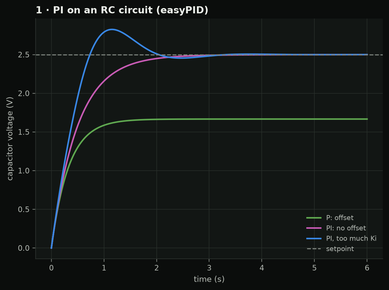
The first two sessions use an Arduino and a resistor-capacitor circuit. A capacitor charging through a resistor is a first-order plant with an exact answer, so a student can predict a P controller’s offset on paper, measure it on the bench, and see the two agree. A three-stage RC ladder then adds enough lag to make tuning interesting: windup, derivative noise, setpoint kick and relay autotuning, each checked against a known result rather than judged by eye.
Every lab uses easyPID, my Arduino library, and the notebooks use a Python port of it. The port is tested against the compiled C++ library on 3,274 randomised updates, so a gain found in a notebook means the same thing in a sketch. Building those tests also found a real flaw: the library’s relay autotuner reports a high ultimate gain on its first run from rest, about 42 against an exact 29, and a good one on the second. The lab now runs it twice.
One drone axis, with the answer key attached
Session three moves to a two-motor seesaw: one axis of a quadrotor on a pivot. The rig has a potentiometer on the pivot, which a real drone never has. Students first close the loop on that clean, absolute angle; in the next session they fuse a gyro and an accelerometer and measure their estimate against the potentiometer. Students get to see exactly how wrong their attitude estimate is, which a flying drone never shows them.
The same rig teaches why drones use cascades. A single loop on the angle swings about 7 degrees when the beam is tapped; an inner rate loop under an outer angle loop holds it to about 3 in the rig model. Students predict that in the notebook before they see it on the bench.
Then the full vehicle, then what breaks
The last sessions are in simulation: the allocation matrix that turns thrust and torques into four motor commands, mixing priorities when the motors saturate, and a position, velocity, attitude and rate cascade. Session six uses my rotor-fault study as its simulator. Students derive why a quadrotor cannot hover once a rotor has lost too much thrust, detect and isolate a fault with CUSUM tests, and watch a yaw-relaxed controller keep a vehicle in the air after a rotor stops.
The capstone is an acceptance test written as code. The same test runs on the rig and on the rig model, so teams tune in simulation first and are scored the same way on hardware. The report asks for the gap between model and hardware, stated plainly.
What is not done
Nobody has taken the course yet. The notebooks run, the sketches compile and the tests pass, but no rig has been built from the documents, and the rig’s parameters come from simulation. The pilot plan lists what the first cohort will measure; until then I can’t say what students learn from it.