ESP32 barn-door star tracker
A 3D-printed camera mount that turns with the sky, so long night-sky photos stay sharp; designed, not yet built.
My partSole designer
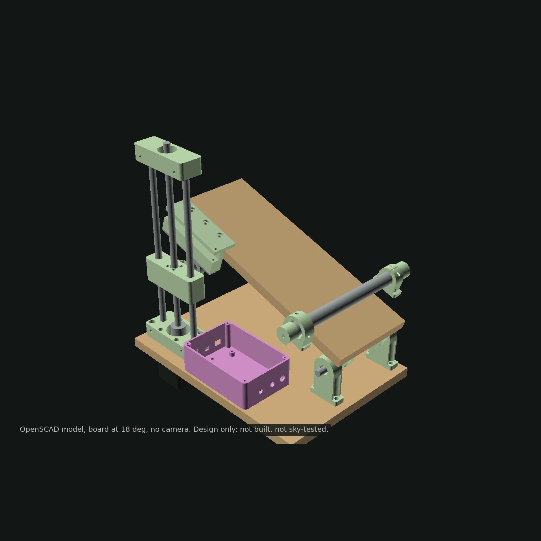
In short
A 3D-printed barn-door tracker for photographing the Orion Nebula with a DSLR. The ESP32 firmware times every microstep from the exact geometry of the mechanism, a Python model predicts the longest sharp exposure for each lens, and a planner picks the night. Designed, compiled and tested in software; not yet built.
- What it is
- An ESP32 barn-door star tracker for DSLR astrophotography: parametric CAD, firmware, a tracking-error model, an observing planner and an autoguiding prototype.
- Why it matters
- The sky turns 15 arcseconds per second, so at 200 mm a fixed camera smears stars in under half a second. Cheap barn-door trackers are simple, but their geometry adds a tangent error that grows the longer they run.
- My part
- I chose the mechanism, derived the geometry, wrote the firmware and the models, and modelled the parts for printing.
Step by step
- 1
Choose the mechanism
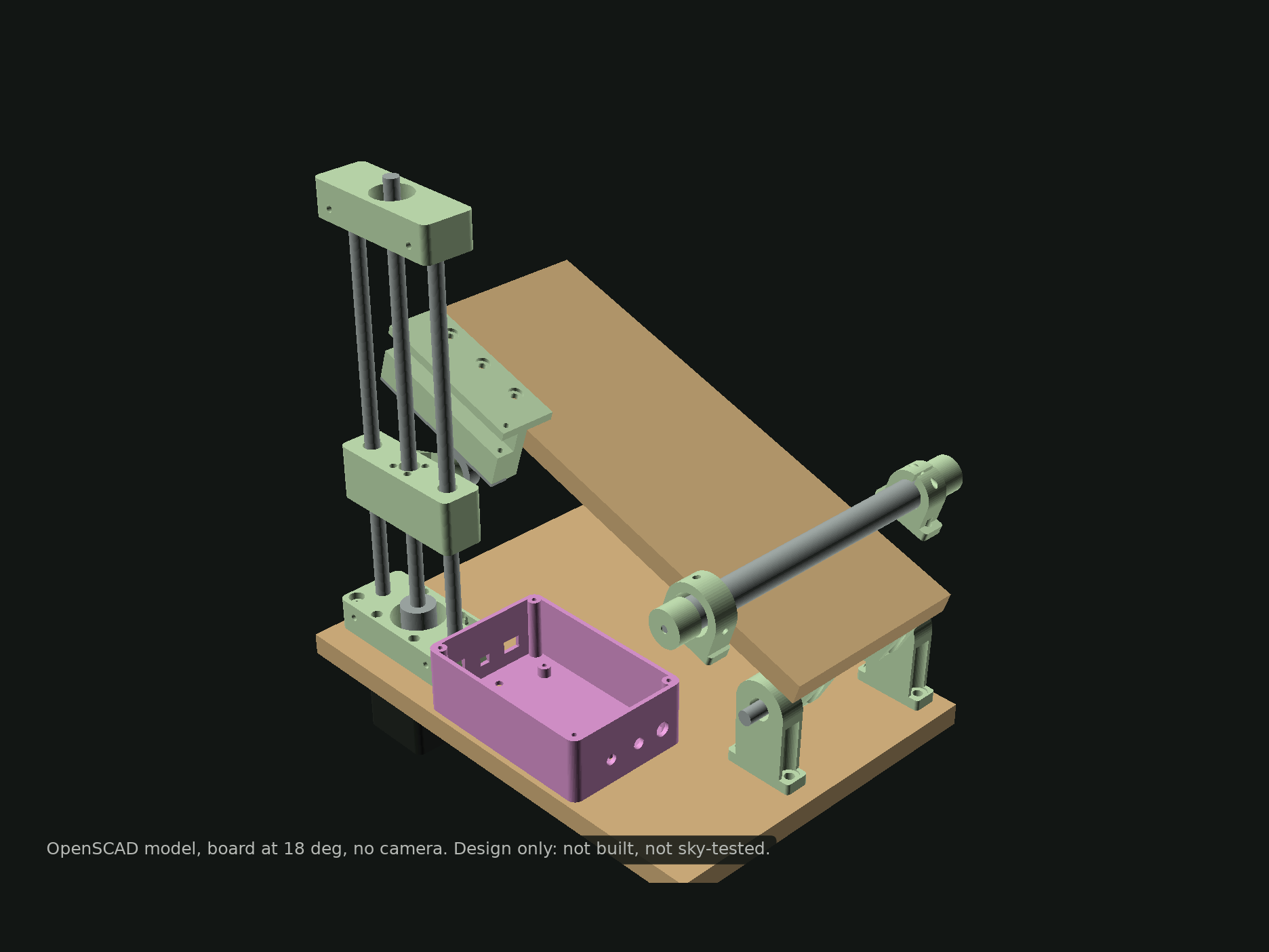
Worm, belt, geared-stepper and lead-screw drives compared by how much they divide motor-side error; a tangent-arm barn door wins at 629:1, 0.64 arcseconds per microstep.
- 2
Let the firmware do the geometry
Position-based microstep scheduling from the inverse kinematics, a 20 kHz integer-only step interrupt, slews, homing, guide pulses, periodic-error correction and an intervalometer.
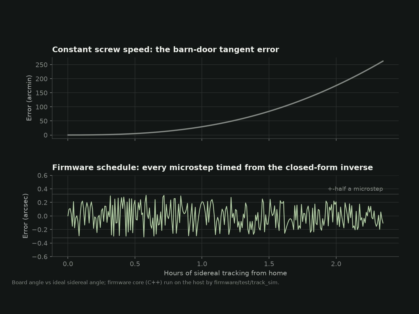
Why the firmware schedules steps: constant speed drifts by degrees; the schedule stays within half a microstep. Host simulation of the firmware code. - 3
Predict before building
An error budget per source, from polar alignment to the screw’s periodic error, converted into the longest sharp exposure per focal length.
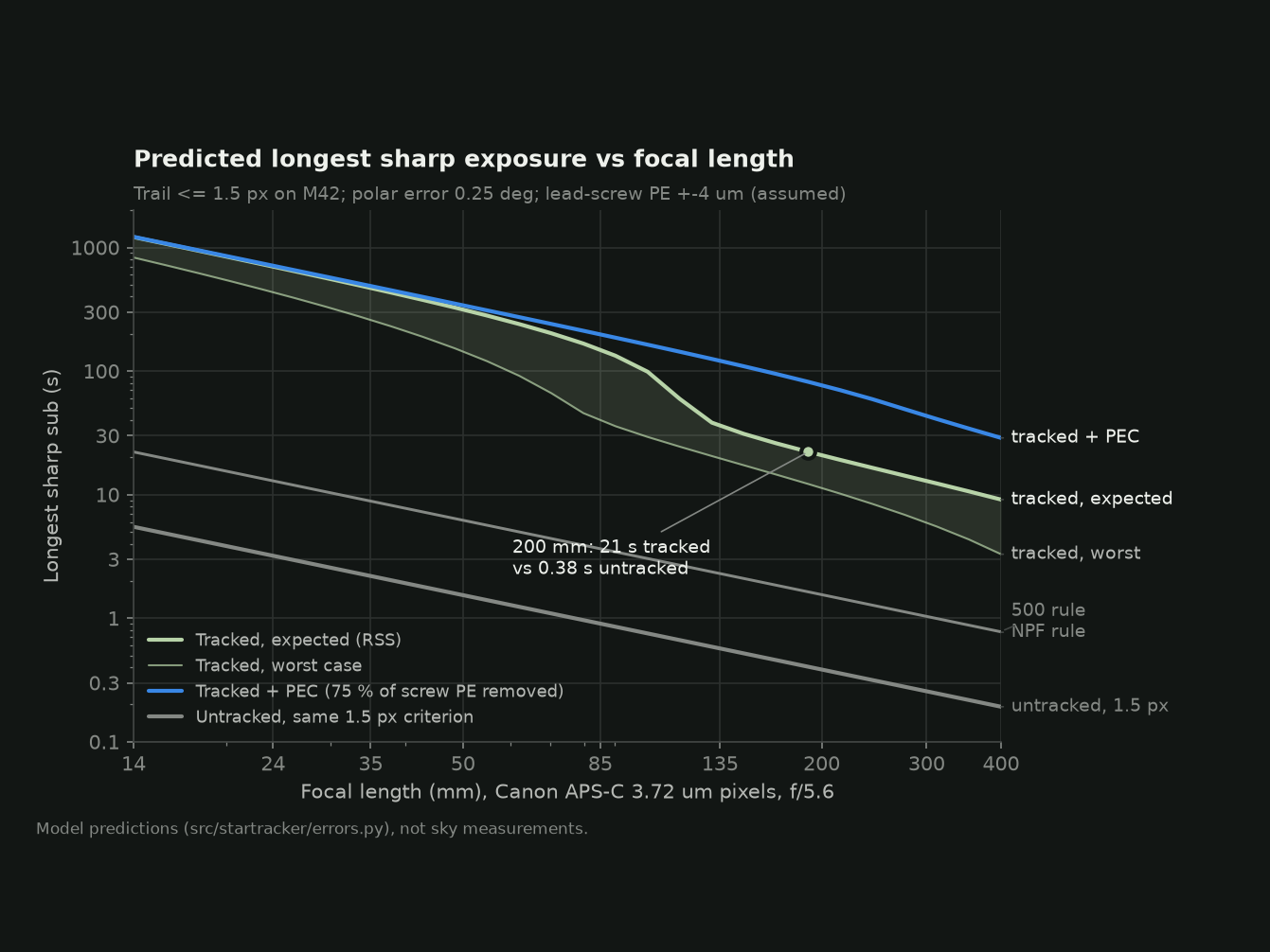
Predicted longest sharp exposure per focal length. Model predictions, not sky measurements. - 4
Plan the night
Every night from October to March scanned with JPL ephemerides for darkness, the Moon and the target’s altitude, ending in a first-session plan.
Results
- ±0.32″
- Tracking residual
- host simulation of the firmware scheduler over a 2 h sidereal run (half a microstep)
- 21 s
- Sharp exposure at 200 mm
- predicted, APS-C 3.72 µm pixels, 0.25° polar error, 1.5 px trail; 0.38 s untracked
- 0.64″
- Per microstep
- design value, 629:1 effective reduction
- 110
- Tests
- 60 C++ on the firmware core under address and undefined-behaviour sanitizers, 50 Python; models checked against JPL ephemerides
For engineersHow it is built, its limits, and its keywords.
How it works
A 2 mm-lead screw pushing a 200 mm arm gives a 629:1 reduction from 3D-printer parts. Instead of running the motor at a speed, the firmware schedules each microstep for the instant the ideal sidereal angle crosses it, using the closed-form inverse of the geometry, so the tangent error is removed exactly and errors cannot accumulate.
Limits
- The analysis panels are verified on simulated signals with known noise, vibration and distortion (the Noise Lab recovers the simulated white noise to within 1 %); long captures from the real unit are still to come.
- Not built and not tested under the sky. Every performance figure is a model prediction.
- The lead screw’s periodic error, assumed ±4 µm, is the largest uncertainty and dominates the predicted budget.
- Single axis: declination drift can be measured, not corrected.
- Polar alignment with the sight tube is coarse, predicted 0.15–0.4°.
- The autoguiding prototype has only seen synthetic star fields.
Keywords
- star tracker
- barn door tracker
- ESP32
- astrophotography
- stepper scheduling