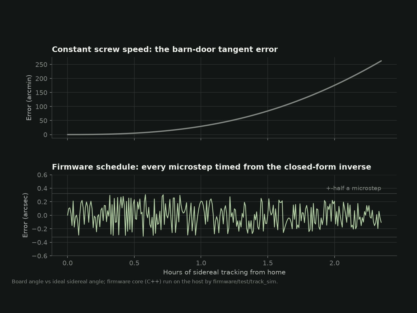
A barn-door tracker is two boards on a hinge. Point the hinge at the celestial pole, open the boards at the rate the sky turns, and a camera on the top board follows the stars. It is the cheapest way to take long exposures of the night sky, and it has one famous flaw: a straight screw pushing a board that swings in an arc does not open it at a constant angular rate. Driven at constant speed, the design in this project would drift off the sky by about 30 arcminutes in the first hour and more than four degrees over its full travel.
The classic fixes are mechanical: a curved rod, or a second arm that cancels most of the error. This design takes the other route. The error is pure geometry, so the firmware can remove it exactly.
Schedule steps, not speed
The firmware never runs the motor at a speed. The geometry of a roller pushing a strike plate gives a closed-form relation between the screw position and the board angle, and its inverse. For each microstep, the firmware computes the instant at which the ideal sidereal angle crosses that step’s true angle and fires the step then. Because every step is placed against the ideal angle rather than added to the previous one, errors cannot accumulate: in a two-hour simulated run of the same C++ code the ESP32 runs, the board stays within half a microstep, 0.32 arcseconds, of the sky.
The ESP32 cannot use its floating-point unit inside interrupts, so the work is split. A 1 kHz task does the trigonometry and fills a small lock-free queue of step times; a 20 kHz interrupt only compares integer timestamps and pulses the driver.
Choosing the drive by division
The deciding argument for the lead screw was division. Every error that starts at the motor, such as uneven microsteps or an eccentric coupler, is divided by the reduction ratio before it reaches the sky. A 2 mm-lead screw pushing a 200 mm arm gives 629:1 from parts sold for 3D-printer Z axes, about 0.64 arcseconds per microstep. Printed worm gears and belt drums reach a fraction of that.
Predicting before building
Nothing has been built yet, so the useful question was what would limit it. A Python error model converts each source, from polar misalignment and drive-rate error to the screw’s periodic error and refraction, into on-sky trail, and from that into the longest sharp exposure for each lens. At 200 mm on an APS-C camera it predicts about 21 seconds per frame, against 0.38 seconds without tracking.
The model also changed the plan. With an assumed periodic error of ±4 µm, the screw’s wobble outweighs polar-alignment error up to about one degree of misalignment. A better polar scope would buy little; a periodic-error correction table, which the firmware already supports, could raise the 200 mm limit to over a minute. That assumption is also the model’s biggest uncertainty, and measuring the real screw is the first job after the build.
What is left
The parts are modelled for printing, the firmware compiles, and the tests pass, but every performance number is a prediction until the tracker is built and pointed at the Orion Nebula. The first session is planned for a moonless window in November. After that, an autoguiding camera, prototyped so far only on synthetic star fields, is the next step.