IMU test bench: live 3D view, noise measurement and calibration
Connect any IMU, flight controller or ROS 2 sensor, see it live in 3D, then measure its vibration, noise and camera alignment.
My partSole author
In short
A real-time workbench for inertial sensors. Connect an Inertial Sense IMX, a PX4 or ArduPilot flight controller, any microcontroller IMU or a ROS 2 topic, and within seconds the device is on screen as a live 3D model, with its raw signals at full rate, its health decoded bit by bit, and its magnetometer calibration laid bare. Then it measures what an integration needs: vibration spectra that expose motor tones and frame resonances, an Allan-deviation Noise Lab that writes the noise model Kalibr asks for, a magnetometer ellipsoid fit it applies to the stream, and a camera view that projects the IMU's horizon into the image and stabilises it by rotation alone. Sensors that only report gyro and accelerometer get attitude from a built-in fusion filter; every session can be recorded, replayed, or republished as standard ROS 2 topics. Developed against a real Inertial Sense RUG-3-IMX-5 for camera–IMU integration on an NVIDIA Jetson, and open source.
- What it is
- A real-time workbench that turns any inertial sensor into a live 3D view, a replayable recording and standard ROS 2 topics, whatever protocol the device speaks.
- Why it matters
- Every inertial sensor arrives with its own protocol, units, axes and vendor tool. Bringing one up can take days before you can even see whether it is pointing the right way, and every new sensor starts that work over.
- My part
- I designed and built all of it: the drivers, the bridge, the fusion, the ROS 2 conversion, the dashboard and the tests, and brought it up on a real IMX unit and on PX4 software-in-the-loop.
Step by step
- 1
Connect
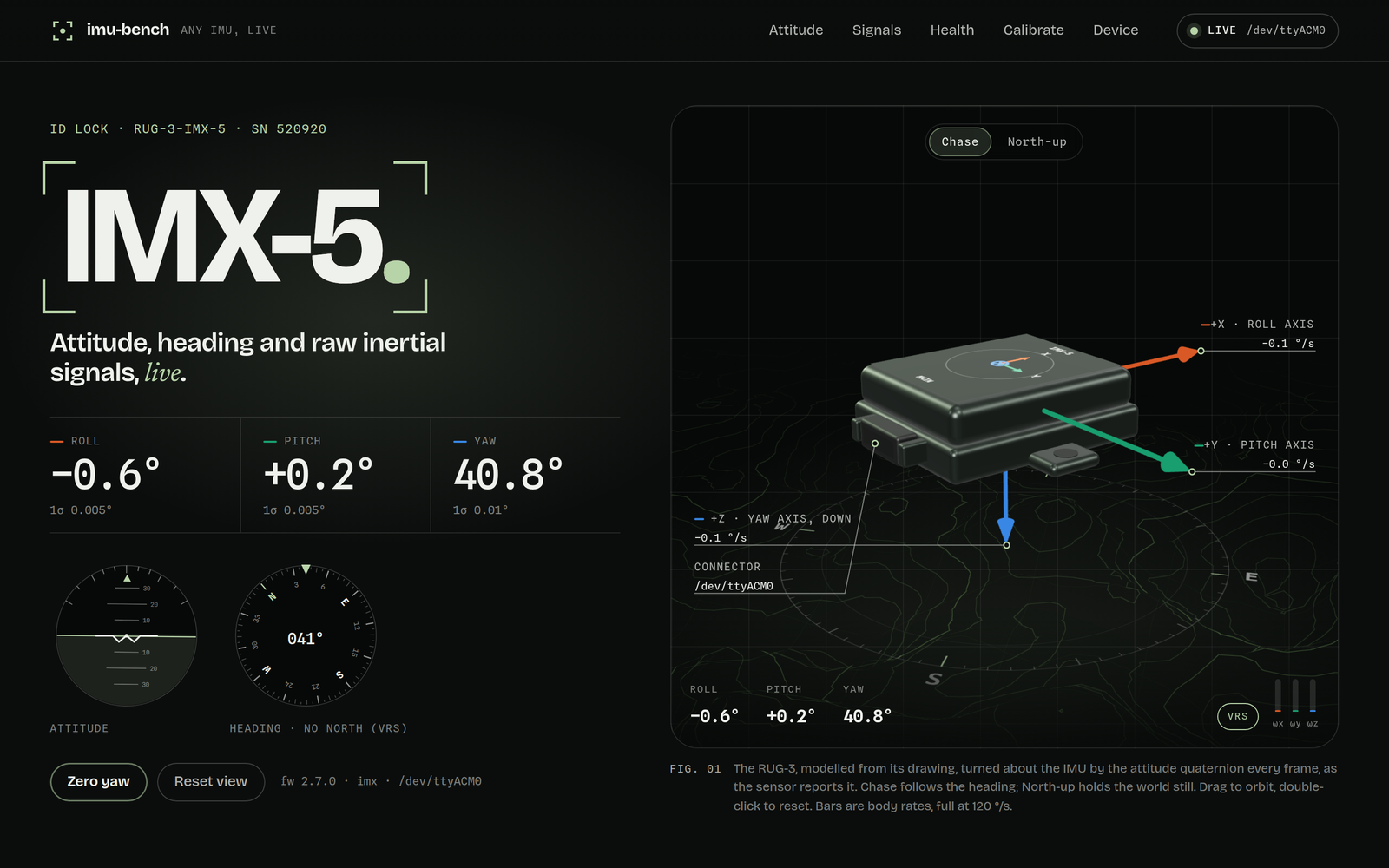
Plug in and go: drivers for the Inertial Sense IMX (found on USB automatically and followed across replugs), MAVLink autopilots, anything that prints JSON or CSV over serial, UDP, TCP or stdin, and ROS 2 Imu topics.
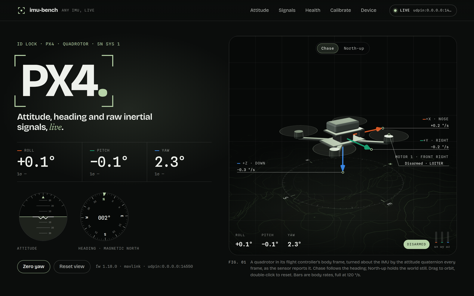
Point it at a flight controller instead: on PX4 1.18 in software-in-the-loop it recognises the vehicle, draws a quadrotor and reads the flight mode and sensor health. - 2
Normalise
Every driver speaks the same few messages (device, attitude, IMU, magnetometer, barometer, status, link) in SI units with an FRD body and a NED world, converted to ROS conventions only at the ROS boundary.
- 3
Fuse
A 6-axis Madgwick filter gives attitude to sensors that only report gyro and accelerometer, with a separate magnetometer heading loop, so a poor calibration can never tilt the horizon.
- 4
Show
The device in 3D as what it really is (an enclosure drawn from its datasheet, a quadrotor, or a breakout board), full-rate strip charts with CSV export, barometric height, decoded health, magnetometer coverage plots and the device's configuration.
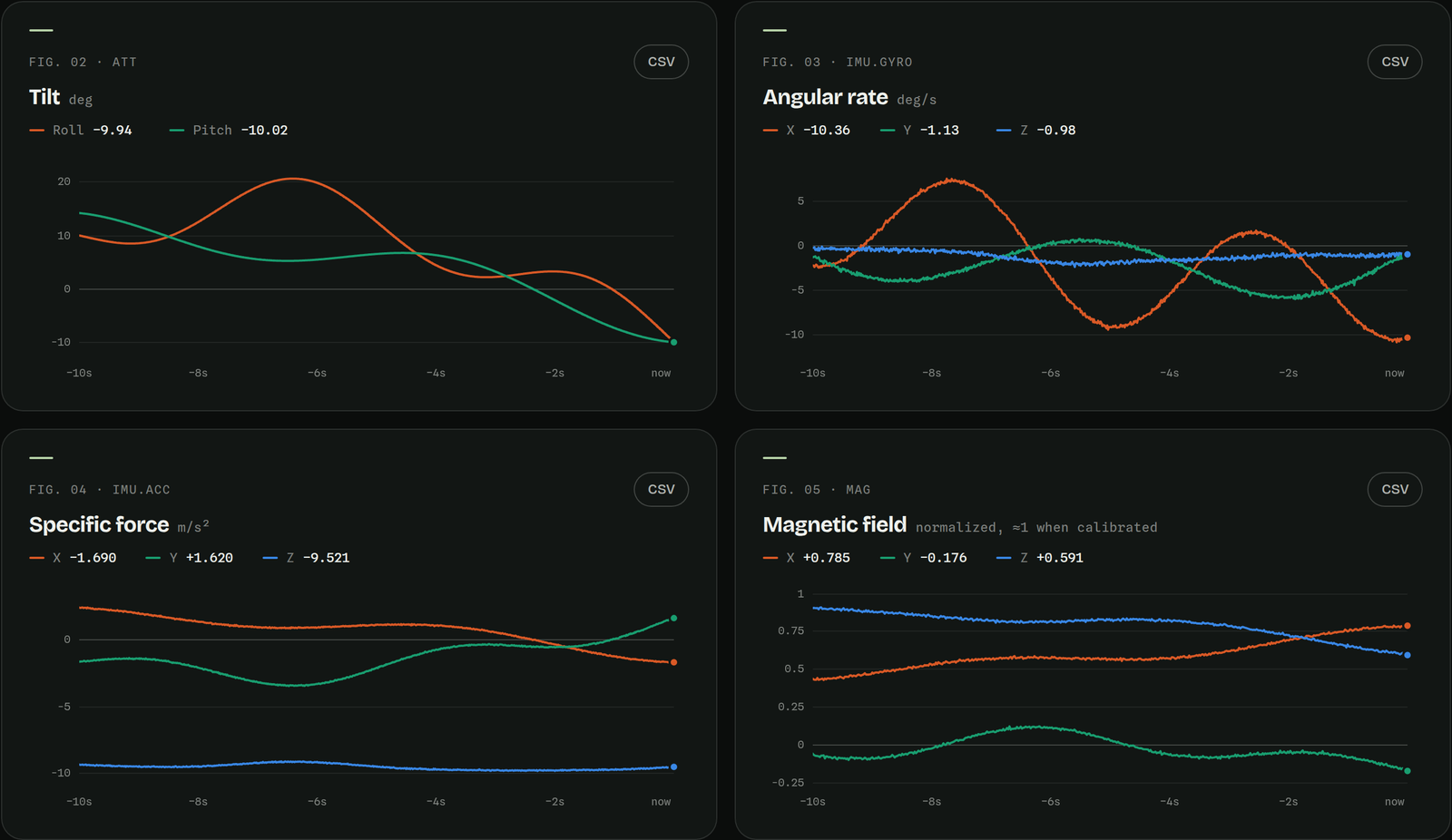
Every signal at full rate, here from the simulator: tilt, angular rate, specific force and magnetic field, each exportable to CSV in one click. - 5
Analyse
Welch spectra and a spectrogram show vibration by frequency; an Allan-deviation Noise Lab reads white noise, bias instability and random walk off a still capture and writes Kalibr's imu.yaml; an ellipsoid fit removes hard and soft iron; and the IMU's horizon, drawn into a synthetic or webcam image, gives the camera–IMU rotation and time offset.
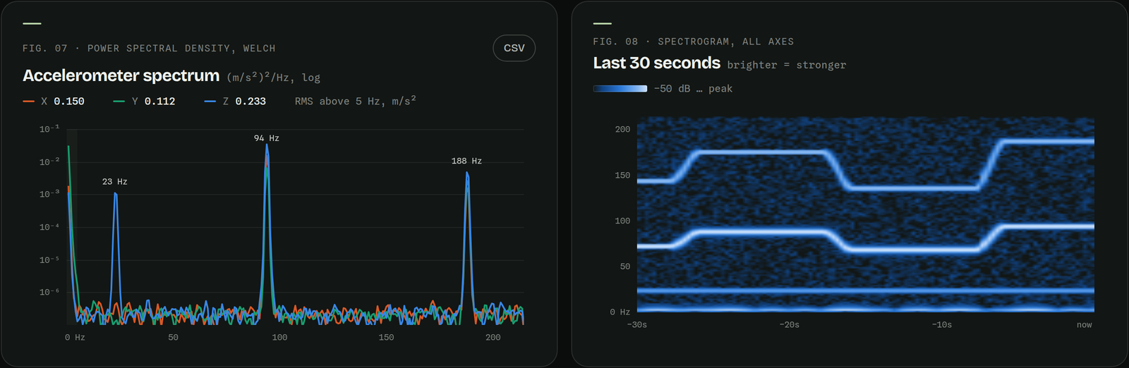
Vibration by frequency, from the simulator: a motor tone and its harmonic stepping with throttle, and a fixed 23 Hz frame resonance. 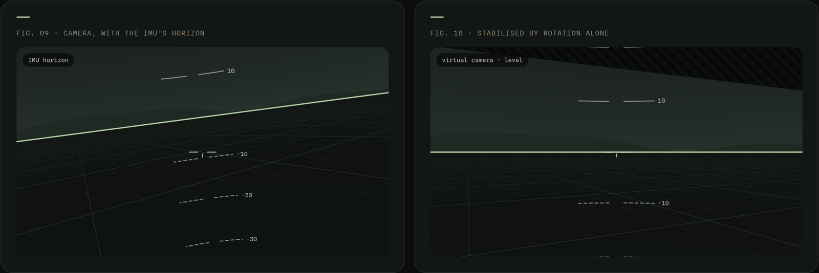
A camera on the IMU, here synthetic: once mount and time offset are dialled in, the predicted horizon sits on the real one and the stabilised view holds level. - 6
Hand on
Record and replay any session, or republish it live as ROS 2 Imu, MagneticField and FluidPressure topics for the rest of the robot. A test suite and continuous integration cover the maths, the parsers and the decoders.
Results
- 1 kHz
- Raw IMU streaming
- from the Inertial Sense RUG-3-IMX-5 over USB at 1.00 ms spacing; attitude at 143 Hz
- 0.12 s
- Hot-plug recovery
- to detect an unplug; the stream is back about 30 ms after the sensor returns, on whatever port it gets
- 0.06°
- Fused tilt accuracy
- mean error on simulated motion with a 0.17 °/s gyro bias; 0.5° heading with a magnetometer
- 0.001°
- ROS 2 fidelity
- attitude error after a full publish-and-subscribe round trip, ROS 2 Jazzy
For engineersHow it is built, its limits, and its keywords.
How it works
A Python core with one driver per protocol translates each device into a small common language: SI units, an FRD body and a NED world. The Inertial Sense driver runs the vendor SDK through a C++ bridge; others speak MAVLink, JSON or CSV lines, or ROS 2. A Madgwick filter supplies attitude when the sensor has none, and a React, three.js and WebGL dashboard brings it all to life in 3D and runs the analysis: FFT spectra, Allan deviation in a background worker, a least-squares ellipsoid fit and pinhole camera geometry, each covered by tests.
Limits
- The analysis panels are verified on simulated signals with known noise, vibration and distortion (the Noise Lab recovers the simulated white noise to within 1 %); long captures from the real unit are still to come.
- Verified on a real Inertial Sense RUG-3-IMX-5 and on PX4 1.18 in software-in-the-loop; ArduPilot and real flight-controller hardware have not been run yet.
- The line driver is verified with synthetic CSV and JSON streams; the bundled MPU-6050 sketch has not yet been run on hardware.
- The fusion accuracy figures come from simulated motion, not a reference rig.
- The video, the chart, spectrum and camera stills on this page come from the built-in simulator; the other stills are a real IMX unit and PX4 software-in-the-loop.
Keywords
- IMU
- AHRS
- sensor fusion
- Inertial Sense IMX-5
- MAVLink
- PX4
- ROS 2
- Madgwick filter
- Allan variance
- Kalibr
- vibration analysis
- camera–IMU calibration
- Python
- C++
- TypeScript
- three.js