Four-cylinder engine simulator
A MATLAB model of a four-cylinder engine, from the motion of its pistons to the gear ratios of the car it drives.
My partSole author · course assignment
In short
A MATLAB simulator I wrote as the main project of the Automotive Engineering course at RHU, in fall 2024. They simulate a four-stroke, four-cylinder spark-ignition engine at 2000 rpm over a full 720° cycle: the slider-crank kinematics, a single-zone thermodynamic cycle, the crank torque of one cylinder and of all four, a flywheel to smooth it, the engine’s performance figures, and the ratios of an eight-speed gearbox.
- What it is
- A MATLAB model of a four-stroke, four-cylinder spark-ignition engine through one full cycle, from the geometry of its crank to the gear ratios of the car it drives.
- Why it matters
- An engine is one chain of dependencies: the crank geometry sets the cylinder volume, the volume sets the pressure, the pressure and the moving masses set the torque, and the torque decides the flywheel and the gearbox. Simulating it means following that chain end to end.
- My part
- I wrote the whole simulator, as the main project of the Automotive Engineering course at RHU in fall 2024.
Step by step
- 1
Parameters
One file holds every input: link lengths and masses, 2000 rpm, valve and combustion timing in crank degrees, gas properties, and the flywheel and transmission constants.
- 2
Kinematics
Piston position, velocity and acceleration, connecting-rod angle and cylinder volume at every crank angle, for a cylinder axis through the crankshaft (compression ratio 9.8) and one offset by −18 mm (10.1).
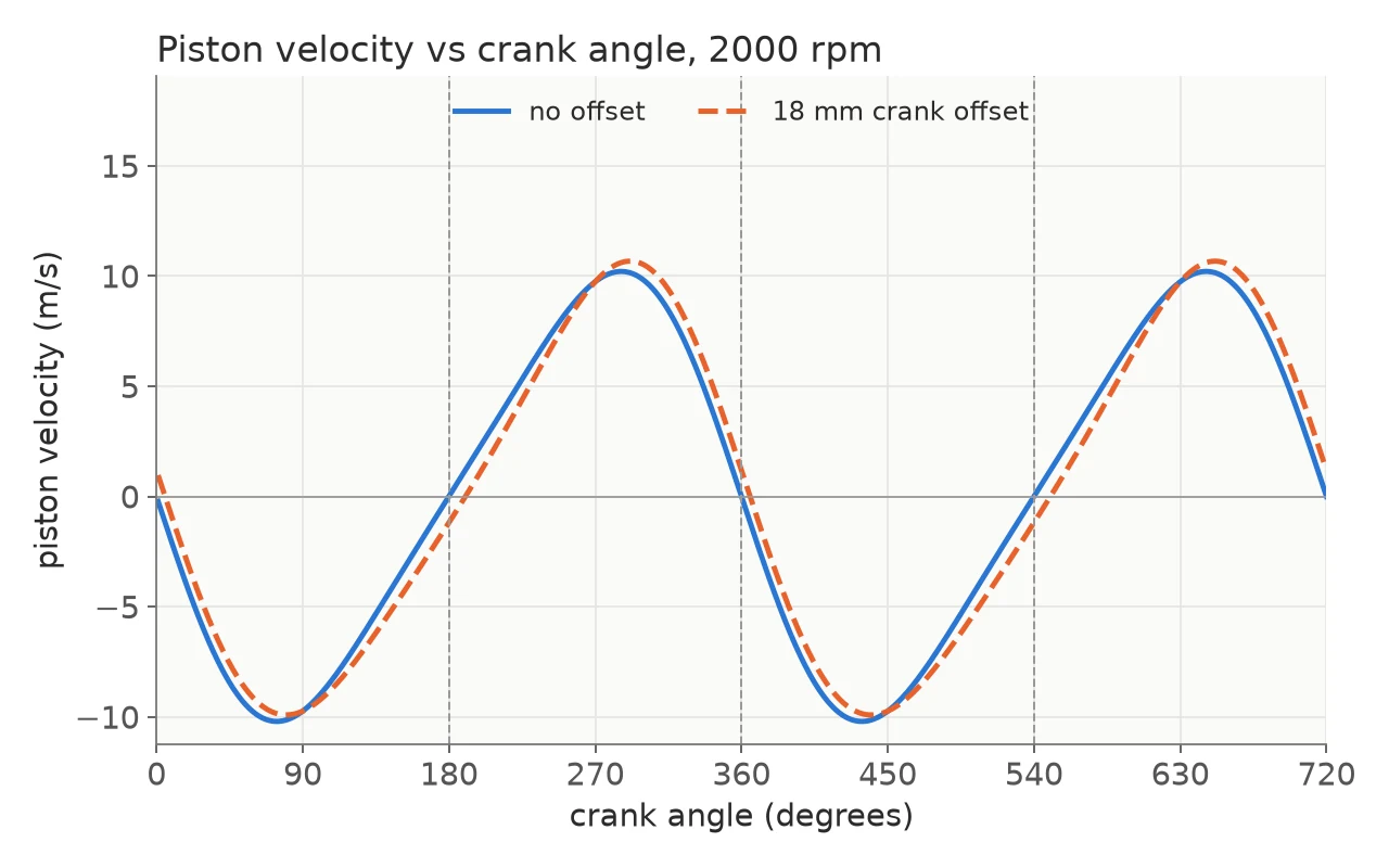
Piston velocity with and without the 18 mm offset. - 3
Thermodynamic cycle
Polytropic compression and expansion; a Wiebe burn (a = 5, m = 2) over 60° around top dead centre toward a constant-volume end-of-combustion state; exhaust blowdown and intake as compressible orifice flow with residual-gas mixing; repeated until the cycle temperature converges.
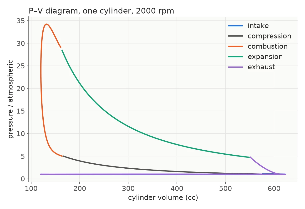
The P–V loop of one cylinder: the work per cycle is its area, about 460 J. 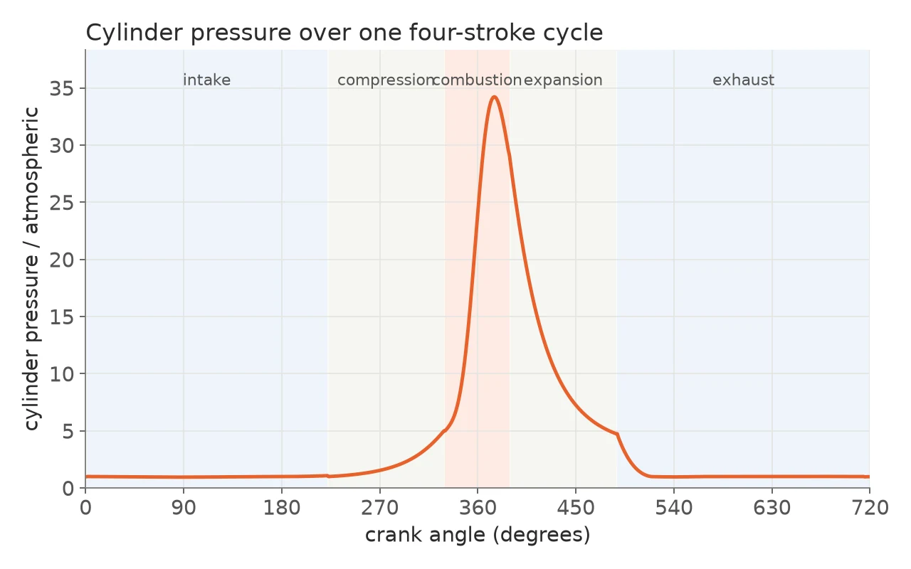
Pressure over the 720° cycle, peaking near 34 atm after ignition. - 4
Torque
At each crank angle an 8×8 linear system of forces and moments, with masses, rod inertia, gravity and gas force, gives the crank torque; four cylinders shifted by 180° are summed.
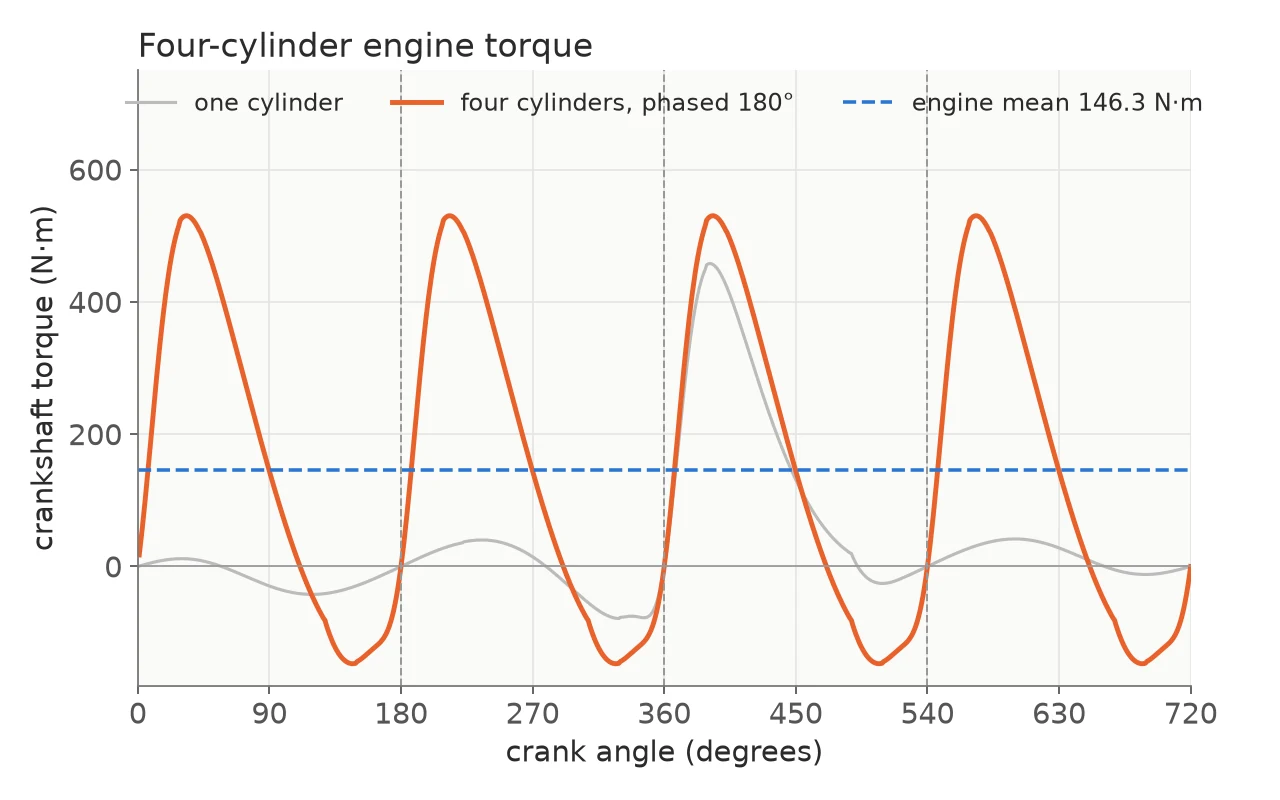
Four cylinders 180° apart: a mean of about 146 N·m. - 5
Flywheel and performance
A flywheel sized from the torque-excess energy for a 0.04 speed-fluctuation coefficient, as a steel disc 50 mm thick; work, indicated and brake power, MEP and BMEP, efficiencies, specific fuel consumption, volumetric efficiency and piston speed.
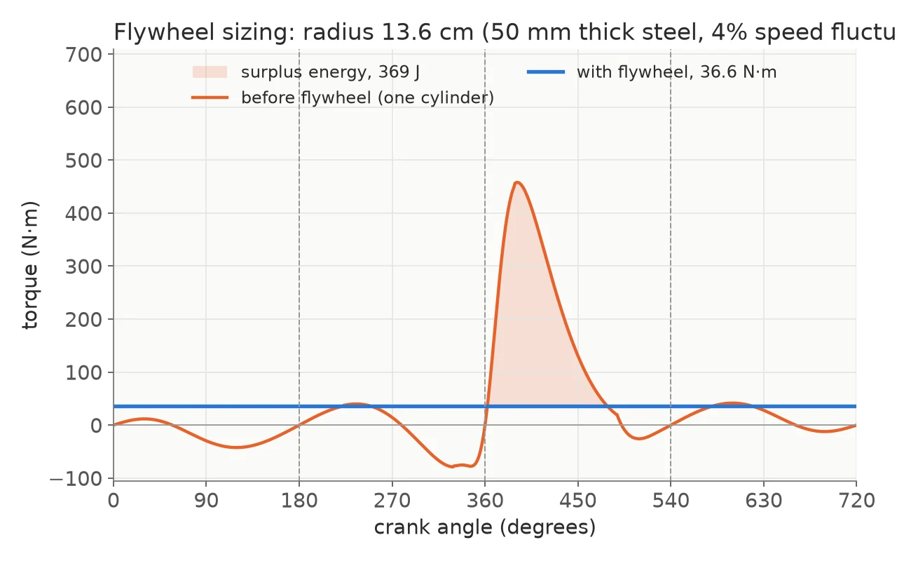
The flywheel absorbs about 370 J of surplus energy per cycle. - 6
Gearbox
Eight gear ratios solved with fsolve between a top speed of 245 km/h and a first gear for a 2600 kg vehicle on a 7 % grade.
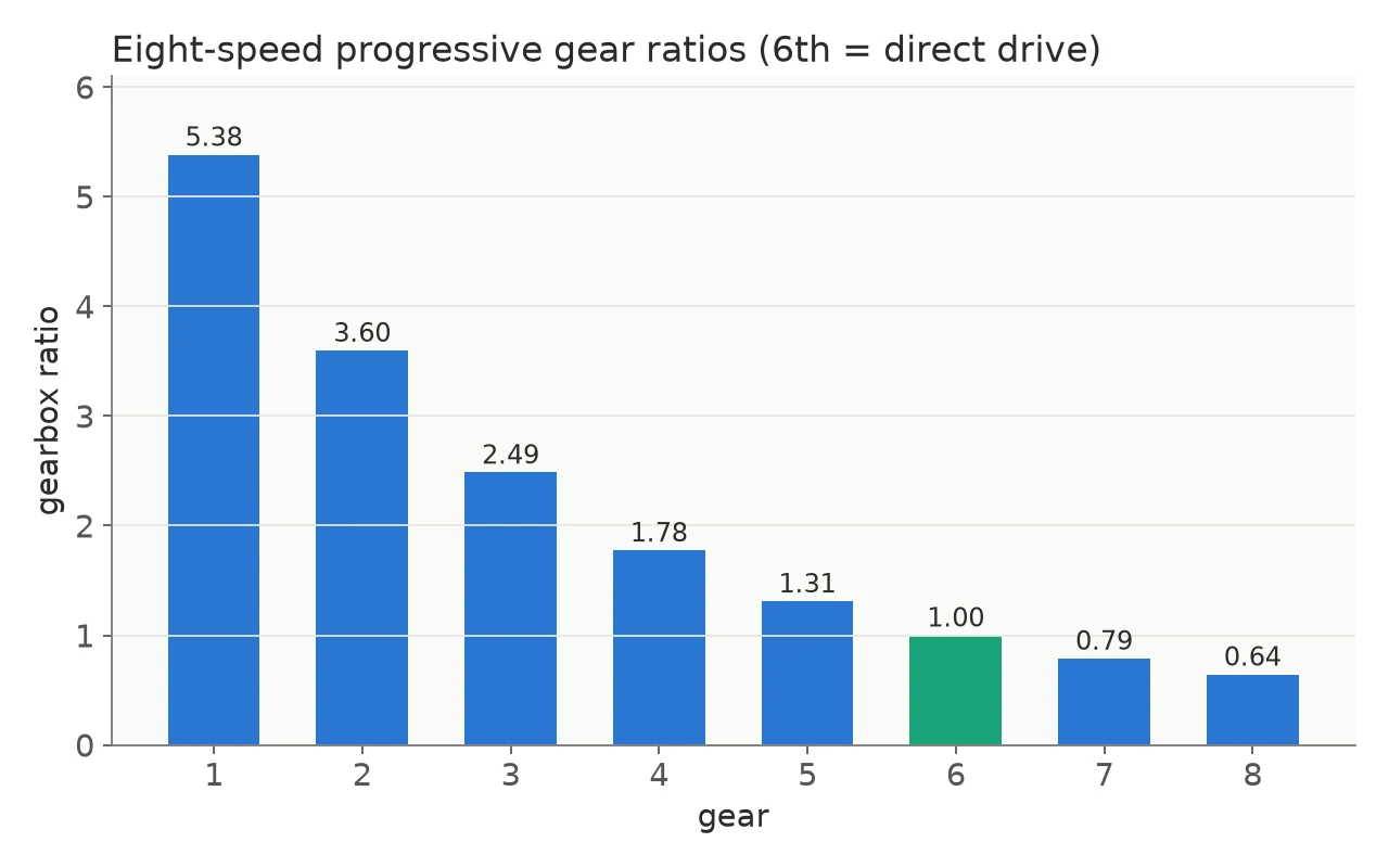
The eight gear ratios, 5.38 down to 0.64, with sixth as direct drive. - 7
Animation
The four slider-cranks drawn moving together, each cylinder flashing as it fires.
Results
- 30.6 kW
- Engine power
- four cylinders at 2000 rpm
- 146 N·m
- Mean torque
- four cylinders
- 28%
- Fuel conversion
- efficiency
- 13.6 cm
- Flywheel
- radius of a 50 mm steel disc, for a 4% speed fluctuation
For engineersHow it is built, its limits, and its keywords.
How it works
One file holds every parameter. A slider-crank solution gives piston motion and cylinder volume at each crank angle. A single-zone cycle with polytropic strokes, Wiebe combustion and orifice-flow gas exchange is iterated until its temperature converges. A linear force and moment solve gives the crank torque, four phase-shifted cylinders are summed, and the result sizes a flywheel and an eight-speed gearbox.
Limits
- The analysis panels are verified on simulated signals with known noise, vibration and distortion (the Noise Lab recovers the simulated white noise to within 1 %); long captures from the real unit are still to come.
- The mean effective pressures the scripts print are about half what they should be: the displacement constant is smaller than the engine’s swept volume of about 503 cc.
- Friction is a flat 10 % of indicated power, and there is no heat transfer to the cylinder walls, no emissions model and no knock.
- The engine turns at one fixed speed, and the speed-fluctuation curve is an idealised sine between the flywheel’s limits, not a simulation of the shaft.
Keywords
- MATLAB
- internal combustion engine
- four-stroke engine
- slider-crank
- engine thermodynamics
- Wiebe function
- flywheel design
- gear ratios